


ENGINEERING CASES / 02
Look inside
the development work.
Three development cases connect an observed issue with a design change, a comparison and the next verification step. Test conditions and outlying observations stay visible alongside the results.
01 / Redesigning the contact for vibration.
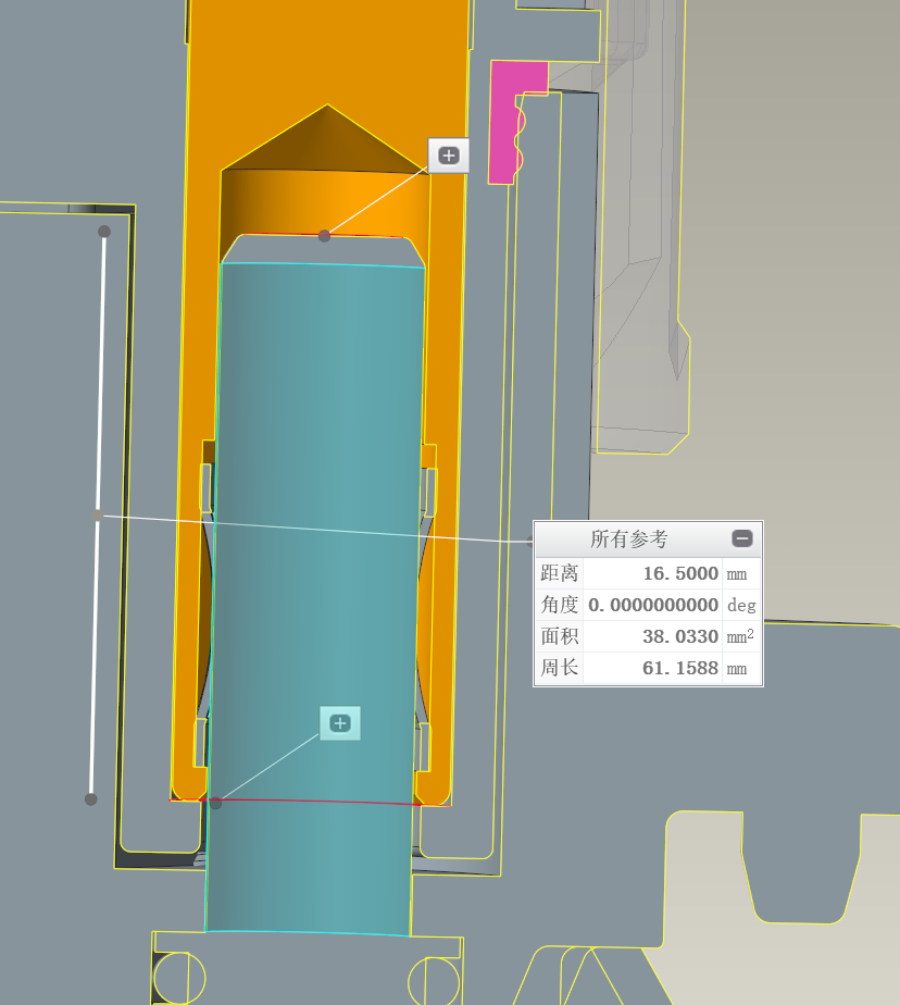
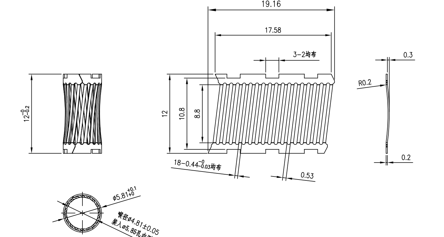
The high-current case described in company material began with temperature-rise and female-contact problems under high-frequency loading, shock and vibration. The revised concept changes the original sample's friction stroke from 8.5 mm to 16.5 mm, modifies the crown-spring curvature, and extends the male contact through the spring into a close-fitting secondary bore to limit relative movement.
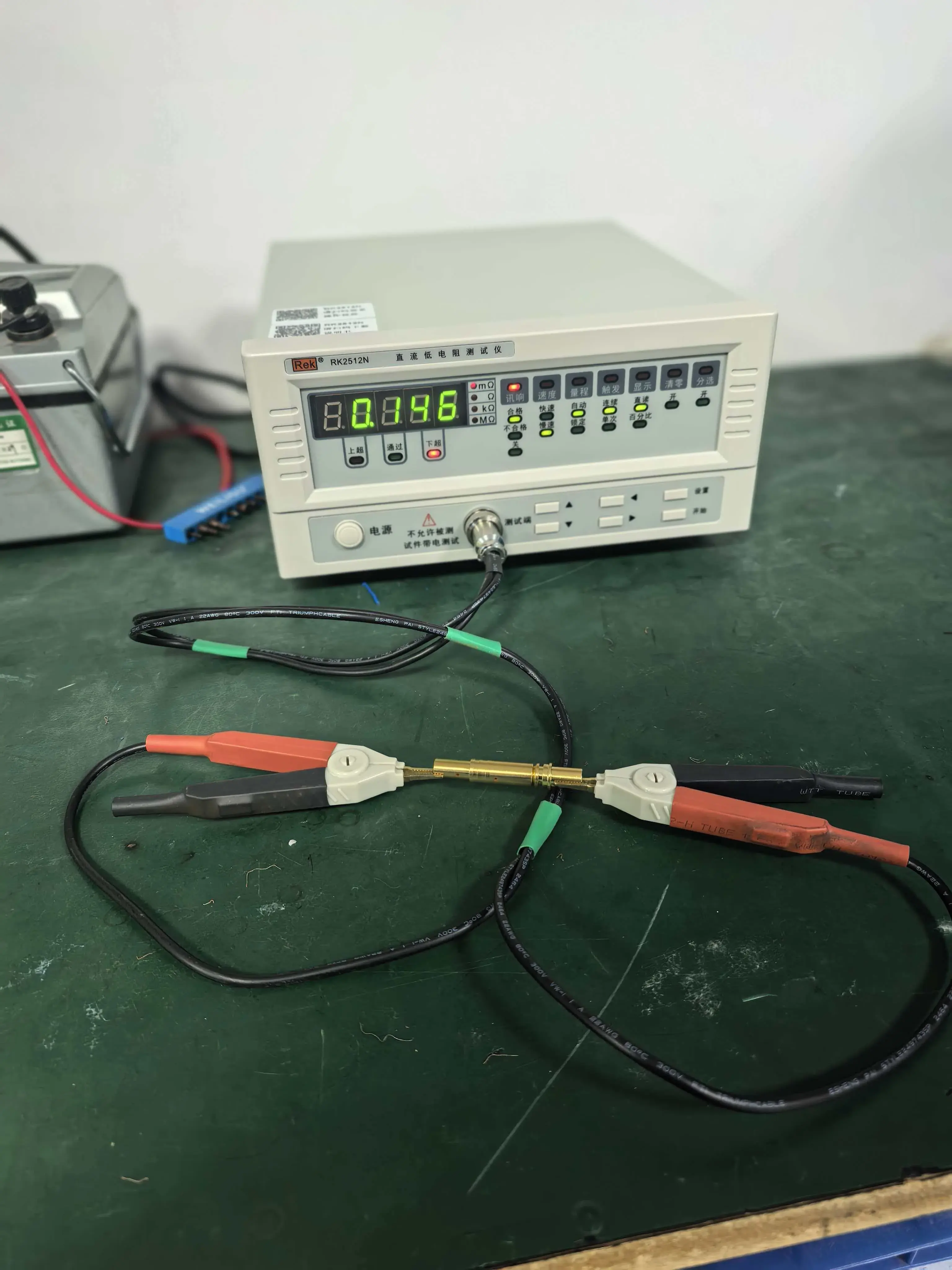
The engineering question is whether contact can be maintained after disturbance. A longer stroke must be considered with spring deformation, mating force and available space. The documented verification plan pairs the geometry change with contact modelling, initial and post-vibration resistance checks, temperature-rise testing and a separate loaded-cable investigation.
Source: October 2026 company presentation, slides 17–18.
02 / M8 sealing: keep the outliers in view.
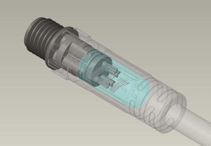
The four-contact M8 fan-interface revision adds a PVC inner overmould in the annular space between insert and housing, with coverage at both ends. Grip ribs move to the outer overmould, while axial recesses and short outer grooves adjust local material volume. Validation compares pressure decay first, then examines electrical behaviour after powered damp heat and temperature cycling.
Swipe the table horizontally to see all columns.
| Measure | No inner overmould | Inner overmould + 0.6 mm ring | Inner overmould + 0.8 mm ring |
|---|---|---|---|
| Samples | 90 | 90 | 135 |
| Mean pressure decay / kPa | 0.006922 | 0.0019 | 0.0009 |
| Maximum pressure decay / kPa | 0.0460 | 0.0464 | 0.0105 |
| Meeting this test's criterion | 88 / 90 | 89 / 90 | 135 / 135 |
The cycle uses 10 s filling, 5 s stabilisation and 10 s measurement, with a pressure-decay criterion of ≤0.03 kPa. All three groups met the criterion at 30 kPa; 60 kPa separated their responses. The 0.6 mm group has a lower mean, but its maximum is not better than the group without an inner overmould. Both the distribution and the exceptions matter.
These figures describe differential-pressure change. They have not been converted to volumetric leak rates and do not establish IP67 or IP68 water-ingress performance.
Source: October 2026 company presentation, slides 19–20, citing tables 1 and 2 of the LLT M8 reliability-validation summary.
After damp heat, examine insulation.
Samples with an inner overmould and 0.6 mm ring were exposed to 85±2 °C and 85±3% RH under a 53 V / 2 A load. Insulation was measured with a 500 V megohmmeter after two hours of recovery. The presentation retains the 720–1000 h observations and separately identifies low-resistance readings excluded from the means.
Swipe the table horizontally to see all columns.
| Duration / h | n used for mean | Mean / MΩ | Low reading excluded from mean / MΩ |
|---|---|---|---|
| 720 | 29 | 646.52 | 3.0 |
| 800 | 30 | 659.13 | — |
| 900 | 30 | 655.40 | — |
| 1000 | 29 | 646.90 | 0.5 |
A high mean does not remove the significance of the 3.0 MΩ and 0.5 MΩ readings. Selection work should ask which sample changed, where a leakage path developed, whether the observation can be reproduced, and how a corrective design will be retested. This excerpt does not establish a lifetime for all samples.
A separate temperature-cycle test used 70 °C and −40 °C, eight hours at each extreme, for nine cycles totalling 144 hours, followed by 72 hours of recovery. Five groups with and five without inner overmoulds met the recorded appearance and functional criteria. This test did not show a clear difference between the two structures.
Source: October 2026 company presentation, slide 21. Means retain the source's stated sample basis; excluded low readings remain visible.
03 / M9 composite sealing and the tolerance stack.
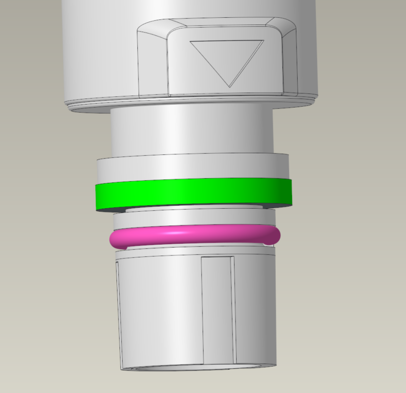
The M9 concept uses a 70 Shore A radial ring for primary sealing and a 40 Shore A face gasket for supplementary sealing and axial preload. Their loading directions, hardnesses and assembly dimensions differ, so each seal needs its own assessment.
Face-gasket compression equals original thickness minus assembled thickness. The three measurements below show how substantially the assembled condition can vary. Quality measurements of the insert, locking parts and seals allow engineering to review the tolerance stack and effective compression range before translating sample experience into batch controls.
Swipe the table horizontally to see all columns.
| Assembled thickness / mm | Original thickness / mm | Compression / mm | Compression ratio |
|---|---|---|---|
| 0.70 | 1.10 | 0.40 | 36.36% |
| 0.75 | 1.05 | 0.30 | 28.57% |
| 0.55 | 1.15 | 0.60 | 52.17% |
These are project measurements, not a recommended 28.57%–52.17% compression range for seals in general. The concept also examines the documented 20° axial cam-rise angle, 155° circumferential guide angle and 0.05 mm local over-compression at the detent. They identify design variables rather than replace the released drawing.
Source: October 2026 company presentation, slides 22–23.
TALK TO ENGINEERING
Bring your application to the conversation.
An installation sketch, operating load, cable details and environmental conditions make a useful starting point.
Contact LLTSelect by parameters →