


RESEARCH / 01
Bring the application
back into the design.
Electrical contact, sealing and retention share a small envelope. LLT engineers examine their interactions separately, then bring them together in a design that can be manufactured and inspected.
Turn operating conditions into testable questions.
A fan interface calls for insulation checks after powered damp-heat exposure. A garden-tool power connection raises questions about contact stability under vibration. A solar-tracking installation adds power, signal and routing requirements. Similar connector sizes can therefore need different validation plans.
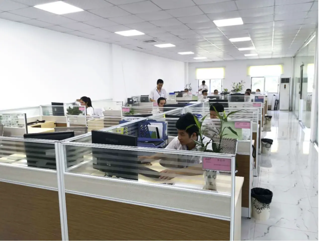
The October 2026 company presentation identifies connector development, mechanical design, modelling and simulation, field application engineering, and cable-process engineering roles. Application engineers translate installation issues into requirements; designers resolve contact, guidance and sealing geometry; process engineers check how those features will be made.
- Define inputs | Current, voltage, wire size, temperature, vibration, media and installation space.
- Develop the concept | Define the contact, sealing path, locking method and tolerance stack.
- Compare samples | Evaluate the original and revised designs under the same conditions.
- Transfer to production | Carry accepted changes into drawings, the BOM, process instructions and inspection requirements.
Contact: the connection is also a heat source.
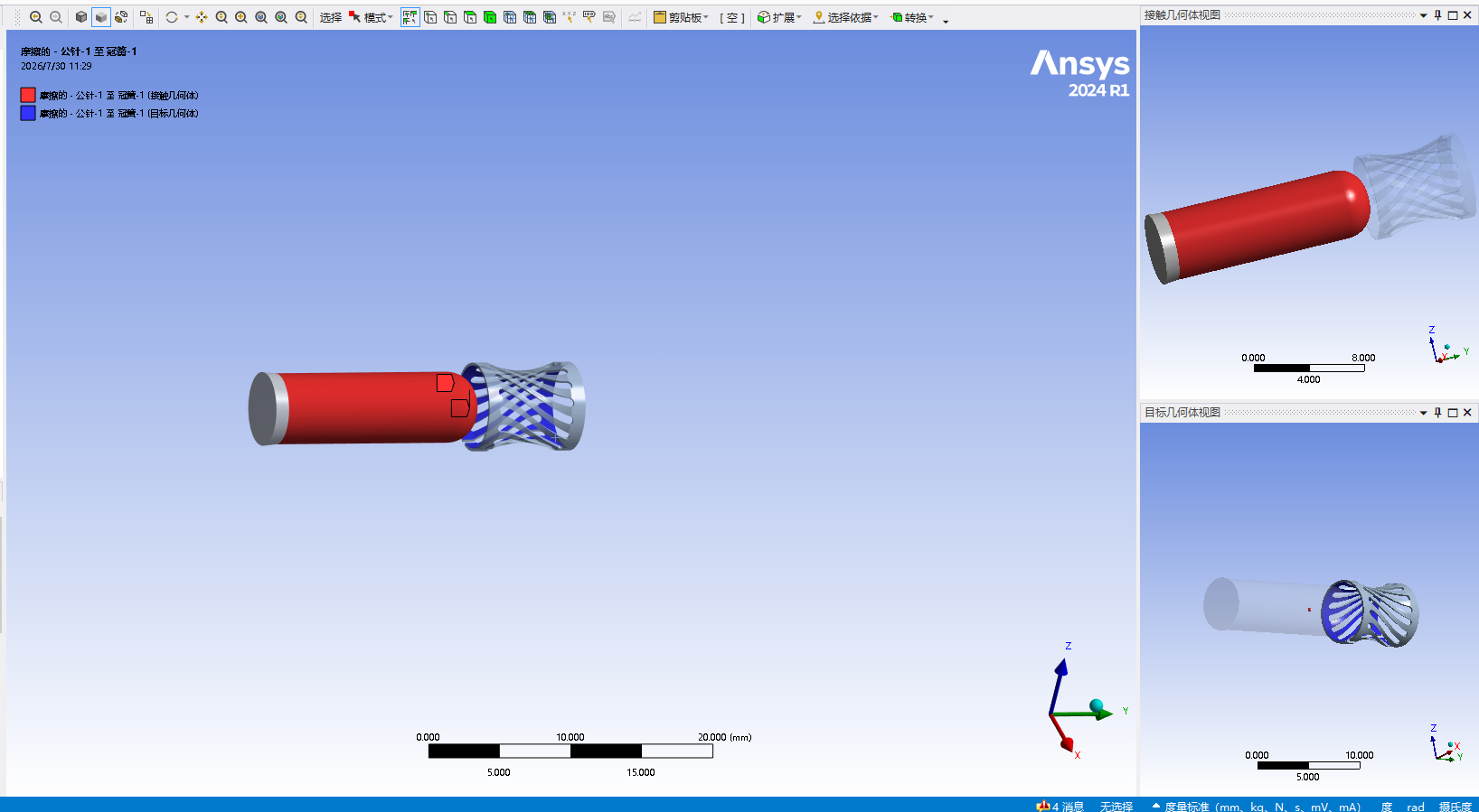
At a given current, contact resistance contributes to heat generation at the interface. An initial reading is only one observation: repeated mating, shock and vibration can change the contact state. Contact stroke, crown-spring geometry and relative movement were design variables in LLT's high-current development case.
The presentation shows Ansys contact modelling and describes electrothermal analysis. Simulation supports comparisons of geometry, local deformation and temperature distribution. Physical checks cover initial and post-vibration contact resistance, temperature rise, and a separate loaded-cable check to distinguish cable heating from interface behaviour.
Sealing: trace the path before setting compression.
Water can enter at the mating face, panel interface or cable entry. An annular gap between the insert and housing can be another path. The M8 revision uses a PVC inner overmould to fill that gap; the M9 concept separates radial-ring and face-gasket functions. These are different structures, not a universal gasket-thickness recipe.
The documented development method includes Abaqus static-seal analysis of contact pressure and its distribution. Samples then undergo differential-pressure screening and relevant environmental tests. Pressure decay can reveal design or assembly differences; it does not directly establish a water-ingress depth. Insulation, continuity and dielectric checks remain necessary after environmental exposure.
Make locking feel traceable to dimensions.
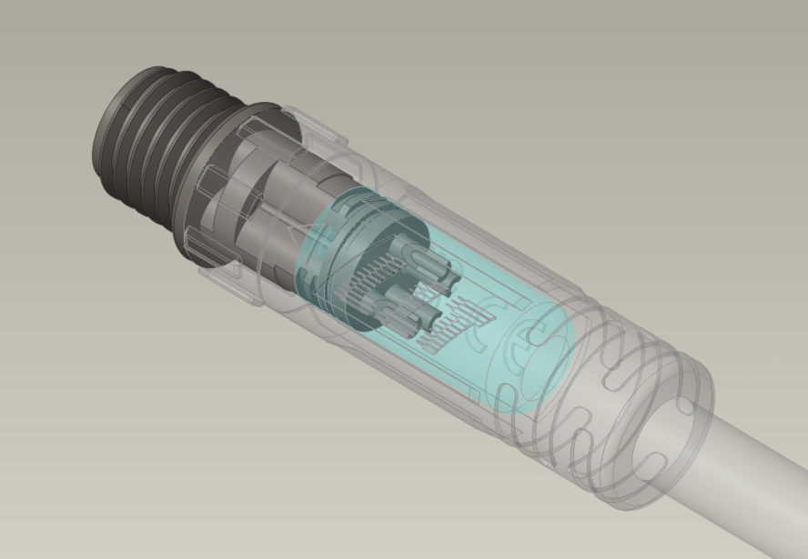
Smooth insertion, a clear rotational stop and positive retention are user experiences. Lead-in angle, guide length, over-centre travel and force–displacement behaviour are engineering variables. The M9 project considers them alongside sealing preload so that assembly force is examined with sealing performance.
A design review needs inspectable outputs: dimensions on the insert, lock and seal; tolerance combinations that affect compression; and a route for tracing batch deviations. Drawings, measurements and sample records must refer to the same revision.
Research accumulates around specific problems.
Representative patents listed in the October 2026 presentation concern latches, self-locking connections, resistance to loosening and connector-life prediction. These records illustrate research directions; they do not independently establish a product's service life or performance in a particular application.
Swipe the table horizontally to see all columns.
| Topic | Publication number | Publication date in the presentation |
|---|---|---|
| Waterproof connector with a latch | CN213242973U | 2021-05-18 |
| Self-locking connector | CN217215329U | 2022-08-16 |
| Photovoltaic connector resisting loosening | CN220456778U | 2024-02-06 |
| Electrical-connector life prediction method and system | CN120334646B | 2025-11-18 |
Source: October 2026 company presentation, slides 12, 14–16 and 28. Legal status and implementation scope require project-specific verification.
TALK TO ENGINEERING
Bring your application to the conversation.
An installation sketch, operating load, cable details and environmental conditions make a useful starting point.
Contact LLTSelect by parameters →